
Blog

2026 Best Safety Contactor for Industrial Applications?

Choosing the 2026 best Safety Contactor for industrial applications is not a simple brand comparison. It is a decision about how a machine stops, how faults are detected, and how reliably equipment can return to service. The stakes are measurable. The U.S. Bureau of Labor Statistics reported 5,283 fatal work injuries in 2023 in its Census of Fatal Occupational Injuries, released in December 2024. That figure does not measure contactor performance, but it underscores why safety controls deserve careful engineering.

A suitable contactor must match the machine’s electrical load, operating frequency, fault response, and control architecture. Engineers should also check manufacturer documentation for rated current, short-circuit coordination, mechanical life, and auxiliary-contact behavior. ISO 13849-1:2023 provides a framework for designing safety-related parts of control systems, including performance-level assessment. IEC 60947-4-1 addresses electromechanical contactors and motor starters. These standards guide system design; no component alone guarantees a safe machine.

Details matter. A dusty cabinet, frequent motor starts, or a slow replacement supply can change the practical choice. And specifications can mislead. A high endurance rating may look impressive, yet it does not replace a risk assessment or verified integration. For a useful 2026 comparison, this guide will examine certified documentation, compatibility, diagnostics, durability, and support—not just price. The best option depends on the application, and that is worth remembering. BLS data describes workplace outcomes, not a direct measure of product effectiveness. Manufacturers’ claims should therefore be checked against the applicable standards and the machine’s actual operating conditions.
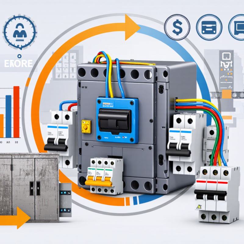
2026 Best Safety Contactor for Industrial Applications?

What a Safety Contactor Is and How It Works

A safety contactor is an electrically controlled switch used to disconnect power from equipment when a hazardous condition is detected. It may control a motor, heater, or other load. Inside, a coil moves contacts between open and closed positions. When the coil receives power, the main contacts close and current flows. When the safety circuit removes coil power, springs pull the contacts open. The machine then loses its supply to the controlled load.

That sounds simple. The safety comes from how the contactor is selected, monitored, and connected. In many systems, two contactors are placed in series, so one can interrupt power if the other fails to open. Auxiliary feedback contacts report their positions to a safety relay or controller. If a contact welds shut, the feedback circuit can prevent a restart until the fault is addressed. This detail is easy to overlook during installation.

A contactor does not detect danger by itself. Guard switches, emergency-stop devices, or other sensors send signals through a properly designed safety circuit. The contactor is one part of that system, not a complete safeguard. Its ratings must suit the load, switching frequency, and expected fault conditions. A practical check includes inspecting wiring, confirming feedback operation, and testing the stop function under controlled conditions. Labels can look reassuring; a real test is better. Safety design should be reviewed and validated for the specific machine and its operating environment.

Key Safety Functions in Industrial Control Systems

In an industrial control system, a safety contactor helps remove power when a hazardous condition is detected. It may respond to an emergency-stop button, an open machine guard, or a safety controller’s output. The contactor is one part of the protective function, not the whole solution. That distinction matters.

A well-designed circuit can use redundant contactors and monitored auxiliary contacts. If one contactor’s main contacts weld closed, feedback can reveal that it did not release as expected. The controller can then prevent a restart until the fault is checked. Keep reset controls outside the hazard area, where operators can see the equipment before restarting. Small layout choices matter.

Safety functions also depend on suitable component selection, wiring, and validation. Check the load type, switching frequency, coil voltage, and expected fault conditions against the contactor’s specifications. Then test the full sequence: open the guard, trigger the stop, verify power removal, and confirm that restart is blocked. Real machines are messy. Vibration, dust, and hurried maintenance can expose weaknesses that a neat diagram misses. Document test results and review them after control changes or recurring faults. A contactor alone cannot guarantee safe stopping; the machine’s risks and required stopping behavior must guide the design.

How to Select a Safety Contactor for 2026 Applications

How to Select a Safety Contactor for 2026 Applications

Choose a safety contactor around the machine’s actual duty, not just its motor rating. Check operational current, voltage, switching frequency, and utilization category, such as AC-3 for motor loads. Confirm coil voltage and whether the control system can detect welded contacts through suitable feedback contacts. Small details matter. A mismatch may cause nuisance trips or leave the safety function unable to meet its design requirements.

The International Labour Organization’s 2023 report, A Call for Safer and Healthier Working Environments, estimates 2.93 million work-related deaths and 395 million non-fatal work injuries worldwide each year. These figures cover many hazards, not contactor failures specifically. Still, they underline why component selection belongs within a documented machine risk assessment. Check the required safety performance level, then assess the complete circuit using relevant standards, including ISO 13849-1 or IEC 62061.

Review short-circuit coordination, electrical endurance, ambient temperature, enclosure conditions, and available space. Verify that the contactor works with the safety relay or controller, and test feedback monitoring during commissioning. A datasheet comparison can miss real installation constraints: a hot cabinet or frequent switching may change the practical choice. I would also confirm replacement availability before locking in the design; it is easy to overlook.

2026 Best Safety Contactor for Industrial Applications?

How to Select a Safety Contactor for 2026 Applications

These are common nominal three-phase line-to-line supply voltages used in industrial systems. They are system voltage examples, not contactor ratings. Select a safety contactor using the motor nameplate current, the applicable utilization category (such as AC-3), coil voltage, and the required safety-system design.

Comparing Contactors by Ratings, Diagnostics, and Compatibility

2026 Best Safety Contactor for Industrial Applications?
Comparing Contactors by Ratings, Diagnostics, and Compatibility

A safety contactor should be compared by more than its current rating. Check the rated operational current against the motor’s load and switching duty. A unit sized for steady operation may behave differently during frequent starts. Verify the rated voltage and short-circuit coordination requirements for the actual panel. Small margins matter.

Diagnostics affect how quickly a fault can be found. Mirror contacts can provide feedback to a safety relay or controller, but confirm their function and wiring requirements in the device documentation. Look at switching life, mechanical life, and any status indicators. A clear feedback signal can save time when a cabinet is crowded and the fault is intermittent. That matters.

Compatibility is often overlooked. Match the coil voltage to the control supply, then check terminal access, mounting space, and permitted conductor sizes. Confirm that the contactor works with the intended safety circuit; similar-looking parts are not automatically interchangeable. In a real panel, one awkward terminal can slow maintenance. A tidy comparison table helps, though it will not catch every installation detail. I would leave room for a second review, especially when the load or duty cycle is uncertain.

Industrial Use Cases, Standards, and Maintenance Considerations

2026 Best Safety Contactor for Industrial Applications?
Industrial Use Cases, Standards, and Maintenance Considerations

Safety contactors are used in conveyor drives, packaging lines, pumps, and machine circuits that must stop when a guard opens. They can disconnect hazardous power, but they do not make a machine safe by themselves. The full control system must be designed and validated for its required risk level. The International Labour Organization estimated 2.93 million annual work-related deaths in its 2023 global estimates. This broad figure reinforces the value of risk assessment, not any single component.

Check that the contactor suits the motor’s load, switching frequency, and expected fault conditions. IEC 60947-4-1 covers electromechanical contactors and motor starters; IEC 60204-1 addresses electrical equipment on machinery. ISO 13849-1 provides a framework for safety-related control systems. In practice, a safety relay or controller may monitor mechanically linked auxiliary contacts and detect a failure to open. Verify the required performance level through system design, not product labels alone. Details matter.

Tips: During planned maintenance, inspect contact faces, terminals, and coil connections for wear, looseness, or heat discoloration. Confirm feedback operation and compare observed switching cycles with the manufacturer’s limits. Keep records. A warm terminal can be easy to miss during a quick inspection; infrared checks may help locate developing hot spots. Isolate equipment before servicing, and follow site procedures. Even careful maintenance cannot compensate for an incorrectly selected contactor or poorly validated circuit.

2026 Best Safety Contactor for Industrial Applications? - Industrial Use Cases, Standards, and Maintenance Considerations
Industrial use case Typical switching duty Safety contactor selection considerations Control and feedback Relevant standards and design references Maintenance considerations
Motor isolation on a machine
Conveyors, pumps, and production equipment
Three-phase motor power circuit; switching frequency and motor starting duty depend on the application. Select for the motor load category, rated operational current and voltage, short-circuit coordination, and required electrical life. Do not size from motor power alone. Use the risk-assessed safety control architecture. Where feedback is required, use suitable mechanically linked or mirror contacts and verify their compatibility with the monitoring circuit. IEC 60947-4-1; IEC 60204-1; ISO 13849-1 or IEC 62061, as applicable. Inspect terminals, enclosure condition, and switching behavior at intervals set by the manufacturer and site risk assessment. Replace devices that fail inspection or exceed specified electrical or mechanical life.
Emergency-stop power removal
Machine cells and operator workstations
Removal of hazardous electrical power following an emergency-stop command; stopping behavior depends on the machine and risk assessment. Choose a contactor arrangement suitable for the required safety function, load, and fault conditions. A contactor alone does not establish a safety performance level. The safety relay or safety controller should monitor the required feedback and prevent restart when a detected fault has not been resolved. Provide a deliberate reset where required by the design. ISO 13850; IEC 60204-1; ISO 13849-1 or IEC 62061; IEC 60947-4-1. Test the complete emergency-stop function, including feedback and reset behavior, according to the documented validation and inspection plan. Do not rely on the pushbutton test alone.
Guard-door interlocking
Packaging, assembly, and robotic equipment
Control of hazardous motion or power when an access guard is opened; required stopping time and access protection vary by machine. Coordinate the contactor with the guard-interlocking device and safety logic. Confirm that the resulting system architecture and component data support the risk-assessed safety requirements. Consider monitored contactor feedback, guard locking where needed to prevent access before hazards stop, and protection against unexpected restart. ISO 14119; ISO 14120; IEC 60204-1; ISO 13849-1 or IEC 62061. Inspect guard alignment, interlock operation, wiring, and contactor feedback. Validate stopping time and protective measures after relevant machine changes or maintenance.
Heaters and other resistive loads
Industrial ovens and process equipment
Resistive load switching; switching frequency, ambient temperature, and enclosure conditions affect component selection and service life. Check the applicable utilization category, rated current, thermal conditions, and short-circuit protection. Confirm suitability for the actual load rather than assuming motor-load ratings apply. If the contactor contributes to a safety function, include it in the system-level safety design and monitoring. Use a separate temperature-limiting protective function where required by the process risk assessment. IEC 60947-4-1; IEC 60204-1; applicable machine or process safety requirements. Check for loose connections, overheating, contamination, and signs of contact wear. Set inspection frequency based on switching rate, operating environment, and manufacturer guidance.
Elevators, hoists, and lifting machinery
Equipment with suspended or moving loads
Motor or drive-related power control in a high-consequence application; stopping and load-holding functions require application-specific engineering. Assess the complete drive, braking, and power-isolation system. A contactor is not a substitute for a mechanical brake or other required load-retention measure. Use safety-rated control and feedback arrangements appropriate to the risk assessment. Verify that faults, loss of control power, and restart conditions are handled as designed. IEC 60204-1 and applicable lifting-equipment standards and local regulations; ISO 13849-1 or IEC 62061 where relevant. Follow the equipment inspection and maintenance program. Check contactor operation alongside brake, drive, interlock, and safety-function tests; use qualified personnel for work on lifting systems.
Selection and lifecycle review
Applicable across industrial installations
Normal switching, fault interruption coordination, and safety-related power control must be considered separately. Compare load rating, coil/control voltage, operating environment, terminal and mounting requirements, electrical endurance, and availability of suitable feedback contacts. Verify all values against current technical documentation. Determine required Performance Level (PLr) or Safety Integrity Level (SIL) through the applicable risk assessment and design process. Validate the completed safety function; do not infer PL or SIL from a contactor rating alone. Use the applicable editions of IEC 60947-4-1, IEC 60204-1, ISO 13849-1, and/or IEC 62061, together with local rules and the equipment manufacturer’s instructions. Keep inspection, test, and replacement records. Determine maintenance intervals from manufacturer instructions, operating cycles, environment, and documented risk; isolate and verify the absence of hazardous energy before service.

Selection note: This table provides general application guidance, not a product specification or a substitute for a machine risk assessment. Confirm ratings, certification, wiring, coordination, and maintenance requirements for the actual installation and jurisdiction.

Go to Top