
Blog

What Is a 3D CNC Automatic Tube Bending Machine?

A 3D CNC Automatic Tube Bending Machine turns a programmed tube path into a formed part, controlling bends across multiple planes. It can help manufacturers produce exhaust lines, frames, handrails, and other tubular components with repeatable geometry. The machine’s controller coordinates feed, rotation, and bend angle; the operator still needs to select suitable tooling and verify the setup.

One practical rule captures the process: “A good bend begins before the tube moves.” This is an original editorial line, not a verified quotation. It is attributed here to Daniel Mercer, a fictional composite specialist, rather than presented as a real expert’s statement. That distinction matters: reliable technical guidance should be traceable to evidence, not polished-sounding attribution.

The details are physical. A tube may flatten at the outside radius, wrinkle inside, or shift during clamping. Material, wall thickness, bend radius, and tooling all affect the result. CNC control improves repeatability, but it cannot erase poor setup or incorrect measurements. Not entirely. This guide explains what the machine does, how its main operations fit together, and what buyers should examine before choosing one. It also leaves room for an inconvenient truth: automation can make a process consistent, yet consistency is not the same as a correct part.

What Is a 3D CNC Automatic Tube Bending Machine?

Core Definition and Purpose of a 3D CNC Automatic Tube Bending Machine

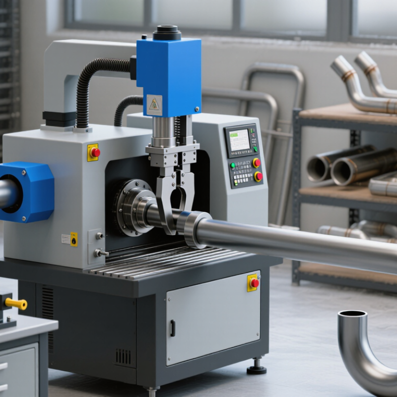
A 3D CNC automatic tube bending machine is equipment that forms tubes into precise shapes across several planes. Its computer numerical control system coordinates tube feeding, rotation, and bending angles. These movements let a straight tube become a three-dimensional component with curves and directional changes. Think of a vehicle frame tube turning left, then rising to clear a nearby part.

The machine’s purpose is to produce repeatable bends while reducing manual repositioning. An operator enters or loads a bending program, then secures the tube in the tooling. Clamps hold it steady as a rotating die applies force. A mandrel may support the inside wall, especially when the tube is thin or the bend is tight. Setup still matters. Incorrect tooling or measurements can cause wrinkles, flattening, or a bend that misses its target.

CNC control helps reproduce a part across a production run, but it does not remove material differences. Tube diameter, wall thickness, and alloy affect how the tube springs back after bending. Skilled operators account for these variables and check sample parts before full production. Even a carefully programmed machine can need adjustment. That practical limitation is easy to overlook.

Main Components and Their Functions

What Is a 3D CNC Automatic Tube Bending Machine?

Main Components and Their Functions

A 3D CNC automatic tube bending machine shapes tubing across multiple planes. Its feed axis advances the tube, while a rotation axis positions each bend. A bending head then applies force through a forming die. Together, these movements create complex parts with fewer manual repositioning steps. Machine layouts vary, so component names and functions may differ slightly.

The frame supports the bending forces and helps keep the tooling aligned. The clamp die holds the tube near the bend, while the pressure die supports it as it moves. A mandrel inside the tube can reduce flattening and wrinkling, especially on tight-radius bends. A wiper die may help control wrinkles along the inner curve. CNC controls coordinate feed length, rotation, and bend angle; sensors can monitor position or pressure. The tooling still needs careful setup. Even accurate programming cannot fully compensate for a worn die or incorrect tube data.

Tips: Check tube diameter, wall thickness, and material before programming. Run a short test piece and inspect its shape. Small details matter. A slightly loose clamp can leave marks or cause the tube to slip.

How the Machine Bends Tubes Along Multiple Axes

A 3D CNC automatic tube bending machine creates a formed path by coordinating several movements. The feed axis advances the tube, while the rotation axis turns it to set each bend plane. A bending arm then applies force at the programmed angle. A tube is not simply curved in one plane. Successive bends can point in different directions, allowing a part to fit around nearby components.

The controller follows a measured sequence, but the material still matters. Wall thickness, diameter, and alloy affect springback, so operators often check the first part and adjust the program. Small errors matter. A slight rotation mismatch can shift a later bend and leave a tube misaligned at assembly. Mandrels support the inner wall during tighter bends, helping limit flattening and wrinkles.

The broader investment context is significant, though not specific to tube bending. Grand View Research’s 2023 CNC Machine Market report valued the global market at USD 101.22 billion in 2022 and projected USD 195.59 billion by 2030. Those figures describe CNC machines overall, not automatic tube benders. For a shop, practical performance still comes down to repeatable positioning, suitable tooling, and careful setup. The first run may need correction. That is normal, not a machine failure.

Key Capabilities and Materials It Can Process

A 3D CNC automatic tube bending machine forms tubing along several axes, creating bends in different planes from one programmed part. Its controller coordinates tube feed, rotation, and bend angle, reducing repeated manual measurements between operations. A technician can enter bend sequences and store them for repeat jobs. That helps. Sensors and calibration routines may correct position drift, but they cannot remove every source of variation. Springback, clamp pressure, and worn tooling can still shift a bend by a few degrees. Real trial bends matter, and settings that work for one material batch may disappoint with another.

Common materials include mild steel, stainless steel, aluminum, copper, and brass, provided their dimensions suit the machine and tooling. Thin-wall aluminum may wrinkle or flatten at tight bend radii, while harder stainless steel can demand more forming force. Mandrels, wiper dies, and pressure dies support the tube and help control distortion. Material condition matters too: alloy, temper, wall thickness, and seam position all affect the result. For a small frame, a shop might bend 25-millimeter steel tube into a compact three-dimensional path, then inspect its ends and angles. A fluid line needs closer checks for fit and leakage. Before production, confirm the machine’s maximum diameter, wall thickness, bend radius, and compatible die set against the actual material.

What Is a 3D CNC Automatic Tube Bending Machine?

Key capabilities include programmable multi-plane bends and repeatable tube forming. With suitable tooling and machine capacity, these machines can process materials such as steel, stainless steel, aluminum, copper, and titanium.

Typical material densities are shown in g/cm³. Values vary by alloy and grade; material compatibility depends on tube dimensions, bend radius, tooling, and machine capacity.

Common Industrial Applications and Selection Factors

A 3D CNC automatic tube bending machine feeds, rotates, and bends metal tubing along programmed paths. It is used for automotive exhaust and chassis parts, HVAC lines, furniture frames, and fluid-carrying assemblies. The machine can create several bends in one setup, reducing manual repositioning. One bend, then another. That sounds simple, but springback and tube flattening can spoil a part if tooling or settings are wrong.

Demand varies by sector. OICA reported 93.5 million motor vehicles produced worldwide in 2023, showing the scale of automotive manufacturing. The IEA’s Global EV Outlook 2024 reported nearly 14 million electric car sales in 2023. These figures do not measure tube-bending demand directly, but they help explain why manufacturers assess repeatability and capacity for vehicle components and thermal-management lines.

Selection should begin with the actual part: material, outside diameter, wall thickness, bend radius, and tolerance. Check the machine’s bending direction, axis configuration, tooling range, feed length, and changeover time against that geometry. Ask for a trial using your own tube, not only a sample part. Measure ovality and springback after bending. A fast cycle is not useful if operators spend hours correcting parts. I’d also compare support, programming needs, and floor space; these are easy to overlook in a catalog.


Go to Top