
How to Choose the Right Electrical Test Kit?
Choosing an Electrical Test Kit is not about buying the instrument with the longest feature list. It is about matching tools to the circuits, measurements, and working conditions you actually encounter. A residential electrician may need a dependable multimeter, voltage tester, and insulated leads. Industrial maintenance can call for a clamp meter, phase-rotation tester, or insulation tester. The difference matters.
Electrical educator Mike Holt is associated with the practical reminder, “Test before you touch.” That habit should guide kit selection, too. Check that each instrument’s measurement range and safety category suit the intended application. Inspect the probe condition, lead insulation, and meter rating; a good-looking case proves little. A proving unit can also help verify that a tester works before and after use. Small details count.
Start with the tasks you perform most often. List the voltage ranges, continuity checks, current measurements, and environments involved. Then compare accuracy, display readability, durability, battery life, and calibration support. If work happens in dim panels, a bright display and backlight are useful. If equipment runs continuously, a clamp meter may reduce circuit interruption. Non-contact testers are handy for quick checks, but they do not replace proper verification with a suitable instrument.
More features are not always better. Nor is the cheapest kit always a bargain. It is easy to focus on specifications and overlook how tools feel with gloves on. That deserves a second look. This guide will help readers compare kit types, safety ratings, essential accessories, and common buying mistakes. The right choice should fit the work—and make careful testing easier.
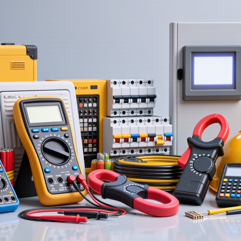
Define Your Electrical Testing Needs
How to Choose the Right Electrical Test Kit?
Define Your Electrical Testing Needs
Before comparing test kits, list the measurements your work actually requires. A maintenance technician inspecting a distribution panel may need voltage, continuity, and resistance functions. A motor specialist may also need current measurement, insulation testing, or phase rotation checks. Be specific. Note the expected voltage range and whether tests happen indoors, outdoors, or in dusty spaces. This simple inventory can prevent paying for features that remain unused.
Next, consider who will use the kit and how readings inform decisions. If several people share it, clear controls and readable displays matter as much as extra functions. Check that each instrument’s range, accuracy, and measurement category suit the task and installation. Do not assume the instrument rating also covers its leads and probes; check those separately. For energized measurements, trained personnel should follow established procedures and use appropriate protective equipment. If circuit conditions are uncertain, pause and verify them with a suitable method. A checklist can still miss a detail, so revisit your requirements after seeing the actual work area.
How to Choose the Right Electrical Test Kit? - Define Your Electrical Testing Needs
| Testing Need | Suitable Instrument | Typical Measurements or Checks | When It Is Useful | Key Selection Considerations |
|---|---|---|---|---|
| General electrical troubleshooting | Digital multimeter | AC/DC voltage, resistance, continuity; current on models with the appropriate input and range | Checking circuits, components, batteries, and basic electrical connections | Choose voltage and current ranges suited to the work. Check the instrument’s measurement category rating, input protection, and lead ratings. |
| Measuring current without disconnecting a conductor | Clamp meter | AC current; some models also measure DC current, voltage, and resistance | Checking load current on an individual conductor in an accessible cable or panel | Confirm AC/DC capability, current range, jaw opening, and measurement category. The clamp normally needs to surround one conductor, not the complete cable. |
| Checking insulation condition | Insulation resistance tester | Insulation resistance using a selected DC test voltage; common selectable voltages include 250 V, 500 V, and 1,000 V on some models | Assessing cables, motors, and electrical installations when the equipment is safely isolated and suitable for the test | Select test voltages and limits according to the equipment and applicable procedures. Verify connected electronics are protected or disconnected as required. |
| Testing low-voltage electrical installations | Multifunction installation tester | Depending on model: continuity, insulation resistance, earth-fault loop impedance, RCD tests, and earth resistance | Inspection and verification work where several installation tests are needed | Check which tests are included, supported system types, measurement ranges, and the requirements of the local electrical code or inspection procedure. |
| Checking for the presence of voltage | Two-pole voltage tester or non-contact voltage detector | A two-pole tester checks voltage between contact points; a non-contact detector indicates a possible electric field near a conductor | Initial voltage checks and, with an appropriate two-pole tester, verifying isolation using the required safe procedure | A non-contact detector does not prove a circuit is de-energized. Use a suitable, correctly rated tester and follow the applicable safe isolation procedure. |
| Testing earth-electrode resistance | Earth resistance tester | Earth-electrode resistance; some models provide clamp-based or selective testing methods | Evaluating grounding electrodes and earthing systems using a method appropriate to the site | Choose a test method suited to the installation and site conditions. Confirm whether auxiliary stakes, access to conductors, or a specific setup are required. |
| Checking circuit frequency or signal behavior | Multimeter with frequency or duty-cycle function; oscilloscope for waveform analysis | Frequency and, on suitable instruments, duty cycle or signal waveform | Troubleshooting AC sources, control signals, and electronic equipment | Check bandwidth, input limits, and probe ratings. Use an oscilloscope when waveform shape or transient behavior matters. |
Measurement ranges and functions vary by instrument. Select equipment with ratings appropriate to the circuit, environment, and applicable safety requirements.


© 2023 JEM Electronics, Inc. – United States Cable Assembly. All rights reserved.