How to Choose the Right Cylindrical Fenders
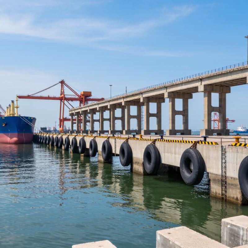
Choosing the right Cylindrical Fenders starts with the berth, the vessel, and the way they meet. UNCTAD’s Review of Maritime Transport 2024 notes that over 80% of world merchandise trade by volume is carried by sea. That scale makes reliable berthing protection more than a minor equipment choice. At a working quay, even a routine approach can bring a heavy hull close to concrete, steel, or adjacent craft.
PIANC’s WG33 Fender Guidelines provide an established engineering framework for assessing berthing energy, reaction force, and fender performance. Use these principles to compare fender diameter, length, rubber properties, fixing method, and available clearance. Vessel displacement matters, but so do approach speed, berthing angle, tidal range, and the strength of the supporting structure. Small details matter. A catalog match can still be wrong for the actual berth. That is worth checking.
Ask suppliers for documented performance data and confirm how their figures were tested. Consider exposure to sunlight, temperature changes, abrasion, and repeated compression; these conditions can affect service life. Inspect existing contact marks and mounting points where possible. Those marks tell a useful story, though not the whole one. A qualified marine engineer should verify the design against site conditions and project requirements. The best choice is not automatically the largest or cheapest fender. It is the one whose verified performance suits the vessel, berth, and operating conditions.
Establish Berthing Energy Using PIANC: E = ½MᴅVʙ²CₘCₑCₛC꜀
PIANC’s berthing-energy method starts with E = ½ MᴅVʙ²CₘCₑCₛC꜀. Mᴅ is vessel displacement, not deadweight; Vʙ is the approach speed. PIANC’s WG 33 Fender Guidelines (2002) gives approximate berthing speeds of 0.15–0.20 m/s for a 50,000-DWT vessel in good to moderate conditions. Site exposure and maneuvering practice still matter. For perspective, a vessel with 100,000 tonnes displacement moving at 0.15 m/s has about 1.13 MJ of uncorrected kinetic energy. The coefficients raise or adjust that value: added water mass, eccentric impact, fender softness, and berth configuration each affect the design load. Small changes in speed matter greatly because speed is squared.
For cylindrical fenders, use the corrected energy to check both absorption capacity and reaction force against the berth structure and vessel hull. A fender may absorb enough energy yet still create excessive hull pressure. Check its rated performance at the actual compression, temperature, and installation conditions; do not rely on a catalogue value alone. The awkward part is estimating real approach speed. Logs can be incomplete, and an exposed berth may behave differently from calm-day observations. Treat assumptions as assumptions, then test a credible higher-speed case. Fender spacing matters, too: contact between fenders can leave an unsupported hull section. The calculation is tidy. The site rarely is.
How to Choose the Right Cylindrical Fenders - Establish Berthing Energy Using PIANC: E = ½MDVB2CMCECSCC
PIANC berthing-energy relationship: E = ½MDVB2CMCECSCC. The examples below use representative vessel displacements and illustrative berthing conditions for preliminary comparison.
| Representative Vessel | Displacement, MD (tonnes) | Berthing Velocity, VB (m/s) | Mass Coefficient, CM | Eccentricity Coefficient, CE | Softness Factor, CS | Berth Configuration, CC | Calculated Energy (kJ) | Preliminary Selection Consideration |
| Small workboat | 500 | 0.15 | 1.8 | 0.50 | 0.90 | 1.00 | 4.6 | Check contact height and fender spacing for the vessel’s hull shape and operating water level. |
| Coastal cargo vessel | 5,000 | 0.15 | 1.8 | 0.50 | 0.90 | 1.00 | 45.6 | Confirm that the fender arrangement accommodates the vessel’s approach angle and the full tidal range. |
| General cargo vessel | 20,000 | 0.15 | 1.8 | 0.50 | 0.90 | 1.00 | 182.3 | Compare the energy requirement with the fender’s rated energy absorption at the expected operating conditions. |
| Container vessel | 50,000 | 0.12 | 1.8 | 0.50 | 0.90 | 1.00 | 291.6 | Check reaction force, hull pressure, and the distribution of berthing loads across the fender line. |
| Bulk carrier | 80,000 | 0.15 | 1.8 | 0.50 | 0.90 | 1.00 | 729.0 | Assess the required energy absorption together with allowable berth-face and vessel-hull reaction loads. |
| Tanker | 150,000 | 0.12 | 1.8 | 0.50 | 0.90 | 1.00 | 874.8 | Verify the design vessel, berthing velocity, contact geometry, and fender performance under site conditions. |
For the examples, CC = 1.00 represents an illustrative open-berth configuration. Energy values are rounded to one decimal place.
Selection note: These are illustrative screening calculations, not project-specific design values. Confirm vessel displacement, berthing velocity, and all PIANC coefficients for the actual site. Select a cylindrical fender system whose energy capacity meets the applicable design requirement, then check reaction force, allowable hull pressure, deflection, fender spacing, contact angle, temperature effects, and mounting conditions.
Match Fender Diameter and Length to Vessel Size and Berth Geometry
A cylindrical fender must suit both the vessel and the space available at the berth. Start with vessel displacement, approach speed, and likely contact angle—not length alone. PIANC’s 2002 Guidelines for the Design of Fender Systems calculate berthing energy from vessel mass and the square of approach velocity, with correction factors for real berthing conditions. That matters: a modest increase in speed can sharply raise the energy the system must absorb. Choose a rated diameter using the supplier’s tested performance data, then check that compression still leaves safe clearance from quay edges and fittings.
Length should cover the vessel’s expected contact zone across changing tides and vessel drafts. Compare the hull’s shape and freeboard with the berth’s layout, fender spacing, and exposed corners. A long fender can spread contact, but it cannot correct poor positioning or a badly placed support. Check the full operating range, including low water and angled approaches. Small geometry differences matter.
Tips: Sketch the berth and mark tide levels, hull contact points, and obstructions. Confirm the chosen diameter’s energy rating and compression clearance against documented test data. Then review the layout with a marine engineer. Field conditions can be messy; plans are not always perfect.
How to Choose the Right Cylindrical Fenders
Match Fender Diameter and Length to Vessel Size and Berth Geometry
How to read this example: The bars show a simple clearance budget: maximum fender projection = measured hull-to-berth gap − a stated 0.30 m reserve. For instance, a 1.20 m gap leaves 0.90 m for projection. These are example measurements and arithmetic, not standard sizing recommendations. Vessel displacement, berthing speed, approach angle, allowable reaction force, and hull pressure must also be checked. Choose fender length to suit the vessel’s contact zone and berth mounting layout; vessel length alone does not determine it.
Compare Energy Absorption and Reaction Force at Rated Deflection
How to Choose the Right Cylindrical Fenders
When comparing cylindrical fenders, check energy absorption and reaction force at the same rated deflection. Energy absorption describes how much impact energy the fender can take in before reaching that point. Reaction force is the load transferred to the berth, vessel, or supporting structure. One number cannot tell the whole story. Energy absorption is represented by the area beneath the force-deflection curve, so compare published values under matching test conditions.
A fender with higher energy capacity may also produce a higher reaction force. That matters. If the structure cannot handle that load, choosing the largest energy rating may create a different problem. Compare the fender’s reaction force with the design limits for the supporting structure, and confirm the expected impact conditions with a qualified engineer. Check dimensions and installation details, too; a gap or uneven contact can change how the fender performs. Not always.
Rated values are useful, but real installations have variation. Temperature, wear, and repeated impacts may affect performance over time. Keep this in mind. Review the full performance curve rather than relying only on a single rated point, and confirm that the rating matches the intended deflection. I would not treat a catalog figure as a complete design check. It is a starting point, and sometimes the less obvious installation detail deserves another look.
Specify Rubber Properties by ASTM D2000 Type, Class, and Hardness
Choosing a cylindrical fender starts with the rubber compound, not just its diameter. ASTM D2000 helps describe that compound through type, class, grade, and hardness. Type indicates heat-aging requirements; class addresses oil resistance. These details matter when a fender faces warm conditions, oily surfaces, or repeated compression. Class does not, by itself, prove suitability for seawater or every marine exposure.
Read the complete callout. The grade relates to tensile strength, while hardness is commonly stated as Shore A. A softer compound may deform more readily, but it can wear differently; a harder one is not automatically safer. Check the fender’s tested load-deflection and energy-absorption data against the vessel’s contact conditions. Also consider temperature range, abrasion, and the actual fluids nearby.
Small details count. A thin oil film near a work area can change the material choice. One easy mistake is specifying a hardness number without defining the other D2000 requirements. It looks precise, but leaves gaps.
Confirm the proposed compound’s test data and service limits before ordering, since a standard designation alone cannot predict performance in every installation.
Check Mounting Loads, Clearances, and Design Criteria Against PIANC WG 33
How to Choose the Right Cylindrical Fenders
A cylindrical fender must absorb berthing energy without imposing excessive reaction loads on the berth or vessel. Start with vessel displacement, approach speed, berthing angle, and the available contact area. PIANC WG 33 provides useful design guidance for assessing energy and reaction, but project conditions still matter. Check which edition and criteria apply to the specific berth. A calculation based on average conditions may miss a demanding arrival.
Mounting details can change how the fender performs. Verify the supporting structure, chains, brackets, and anchor points against the expected reaction loads. Then check clearances across the full tidal range. At low water, a fender may contact a narrow part of the hull; at high water, chains or brackets may interfere with access. Allow for vessel movement and realistic approach angles. Easy to miss.
Compare the fender’s energy capacity and reaction with the design criteria, including appropriate correction factors and safety allowances. Confirm that hull pressure remains acceptable at the actual contact footprint. Drawings help, but site measurements can reveal projections, uneven faces, or worn steel that plans omit. Record these conditions before finalizing the arrangement. A small clearance discrepancy is not automatically harmless; it deserves a second look.