
What Are the Top 10 Types of Wind Grid Inverters?
Wind energy is no longer defined only by turbine size or blade design. The converter behind the turbine strongly influences grid stability, energy yield, and maintenance demands. A Wind Grid Inverter changes variable electrical output into controlled power suitable for modern transmission and distribution networks. Its behavior becomes especially important during voltage dips, frequency changes, and sudden wind fluctuations.
Professor Frede Blaabjerg, a leading power-electronics researcher at Aalborg University, has described power electronics as “the enabling technology for renewable energy systems.” This observation explains why inverter selection deserves careful technical attention. Different applications may require doubly fed induction generator inverters, full-converter systems, modular multilevel inverters, or low-voltage and medium-voltage designs. Each type offers a different balance between efficiency, fault response, cost, and service complexity.
The practical differences are visible in the field. A coastal wind farm may face salt exposure, strong gusts, and difficult maintenance access. An offshore project may prioritize redundancy and fault tolerance above a small efficiency gain. Grid codes also vary by region, so one successful design may not fit every network. That point is easy to overlook.
No classification is perfect.
This guide examines the top ten types of Wind Grid Inverter technologies and explains where each design fits. It considers operating principles, common applications, advantages, limitations, and real engineering trade-offs. Some categories overlap, and several systems can be combined. That is not a weakness; it reflects how rapidly wind-conversion technology continues to develop.
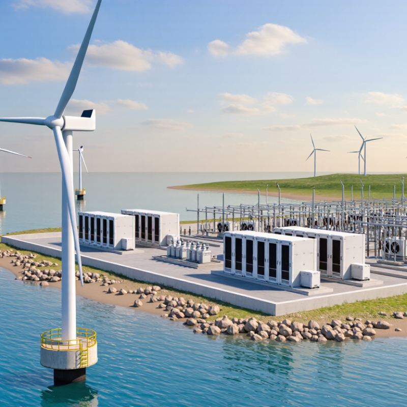
Wind Grid Inverters: Role, Structure, and Core Operating Principles
Wind grid inverters connect variable wind energy to a stable electrical network. They regulate voltage, frequency, active power, and reactive power during changing wind conditions. The top ten types commonly include doubly-fed, full-converter, direct-drive, permanent-magnet, squirrel-cage, wound-rotor, synchronous, neutral-point-clamped, modular multilevel, and grid-forming inverters. These categories can overlap.
The structure usually contains semiconductor switches, a DC link, control boards, sensors, cooling parts, and an AC filter. A doubly-fed design connects part of its power electronics to the rotor circuit. A full-converter design processes nearly all generator power. Direct-drive systems remove the gearbox, but their converters often handle higher currents. That changes cooling and maintenance demands.
During operation, the controller measures voltage, current, rotor speed, and grid angle. A phase-locked loop helps synchronize the inverter with the grid. Pulse-width modulation then shapes the output waveform. Maximum power tracking adjusts generator torque as wind speed changes. Reactive-power control supports voltage stability. Grid-forming control can create a voltage reference in weaker networks, while grid-following control depends on an existing grid signal.
Field testing shows that clean waveforms do not guarantee reliable operation. Harmonic filters may heat unexpectedly. Sensors can drift. Protection settings also require careful coordination. In practice, classification is imperfect because one inverter may combine several operating methods. Depth matters more than labels.
What Are the Top 10 Types of Wind Grid Inverters? — Wind Grid Inverters: Role, Structure, and Core Operating Principles
Wind grid inverters convert variable-frequency electrical power from a wind turbine into grid-compatible AC power. The following types are classified by converter architecture, semiconductor topology, control method, and wind-turbine integration.
| No. | Wind Grid Inverter Type | Typical Wind-Turbine Interface | Basic Structure | Core Operating Principle | Main Grid-Support Functions | Key Advantages | Main Limitations | Typical Use |
|---|---|---|---|---|---|---|---|---|
| 1 | Doubly-Fed Induction Generator (DFIG) Converter Partial-scale Back-to-back | Wound-rotor induction generator with a rotor-side power converter. | Rotor-side converter, DC-link capacitor, grid-side converter, rotor slip rings, and step-up transformer. | The rotor converter controls rotor currents and electromagnetic torque, while the grid-side converter regulates DC-link voltage and reactive power. Only the slip power passes through the converter, normally a fraction of total turbine power. | Reactive-power control, voltage regulation, active-power control, and limited low-voltage ride-through support. | Lower converter power rating and reduced converter losses compared with a full-scale converter. | Slip rings require maintenance; grid behavior is more directly affected by the generator and is less flexible than a full-converter design. | Variable-speed wind turbines where a partial-scale converter is acceptable. |
| 2 | Full-Scale Permanent-Magnet Synchronous Generator (PMSG) Converter Full-scale Gearless or geared | Permanent-magnet synchronous generator, usually with a full-power AC/DC/AC converter. | Generator-side PWM converter, DC-link capacitor, grid-side PWM inverter, filters, and transformer. | All generator power is processed through the converter. The generator-side stage controls torque and generator current, while the grid-side stage creates synchronized AC power with controlled voltage, frequency, and reactive power. | Wide-speed operation, strong electrical decoupling from the grid, high efficiency, and good controllability. | Permanent magnets increase material cost and may require careful thermal management; the converter must be rated for full turbine power. | Modern variable-speed turbines, including direct-drive and medium-speed configurations. | |
| 3 | Full-Scale Electrically Excited Synchronous Generator Converter Full-scale Adjustable excitation | Wound-field synchronous generator connected through a full-power converter. | Generator-side converter, DC link, grid-side inverter, field-excitation system, output filter, and transformer. | The converter controls generator torque independently of grid frequency. The field winding provides adjustable magnetic excitation, while the grid-side inverter controls the exported current. | No permanent magnets are required; excitation can be adjusted for operating-point and voltage-control needs. | Field winding and excitation equipment add electrical losses, control complexity, and maintenance requirements. | Large variable-speed wind turbines where controllable excitation and full grid decoupling are important. | |
| 4 | Full-Scale Induction Generator Converter Full-scale Induction machine | Squirrel-cage induction generator connected to a full-power converter. | Induction generator, generator-side AC/DC converter, DC-link capacitor, grid-side DC/AC inverter, filter, and transformer. | The converter isolates the generator from grid frequency and voltage variations. Generator-side control regulates torque and speed, while the grid-side stage manages active and reactive current. | Robust rotor construction, no brushes or slip rings, and complete electrical decoupling from the grid. | Reactive magnetizing current is required; efficiency and power density may be lower than those of some permanent-magnet systems. | Variable-speed wind turbines requiring a rugged, brushless generator. | |
| 5 | Two-Level Voltage-Source Inverter (VSI) PWM Three-phase | Most commonly used as the grid-side stage of a back-to-back wind converter. | Six controllable semiconductor switches, a DC-link capacitor, anti-parallel diodes, AC filter, and grid transformer. | The inverter switches the DC-link voltage between positive and negative values to synthesize three-phase AC. PWM controls the fundamental current and suppresses unwanted harmonics through filtering. | Simple structure, mature control methods, compact size, and broad availability of power modules. | Higher device voltage stress and greater switching ripple than multilevel alternatives; filtering can become substantial at high power. | Low- and medium-power wind converters and many conventional full-scale systems. | |
| 6 | Three-Level Neutral-Point-Clamped (NPC) Inverter Multilevel Medium voltage | Full-scale wind converters and medium-voltage grid interfaces. | Split DC link, clamping diodes, three voltage levels per phase leg, AC filter, and transformer or medium-voltage connection. | The inverter generates positive, zero, and negative voltage levels. Sharing the voltage across more semiconductor devices reduces output voltage steps and improves waveform quality. | Lower device voltage stress, lower switching harmonics, and improved efficiency at medium-voltage power levels. | Neutral-point voltage balancing is required; the circuit uses more components than a two-level inverter. | Medium- and high-power wind turbines connected through medium-voltage collection systems. | |
| 7 | T-Type Three-Level Inverter Multilevel Low-loss switching | Full-scale wind converters, especially low- and medium-voltage applications. | Three-level phase legs using bidirectional or clamping switches, a split DC link, output filter, and transformer. | By selecting three output voltage levels, the inverter reduces voltage steps and current ripple. The switching strategy distributes semiconductor losses among the available devices. | Low conduction and switching losses, improved waveform quality, and high efficiency in suitable voltage ranges. | Control and protection are more complex; semiconductor voltage ratings and neutral-point balancing must be carefully coordinated. | High-efficiency wind power converters operating at low- to medium-voltage levels. | |
| 8 | Modular Multilevel Converter (MMC) Modular High voltage | High-power wind turbines, medium-voltage wind farms, and offshore transmission interfaces. | Series-connected submodules in each converter arm, arm inductors, distributed capacitors, control system, and grid transformer or reactor. | Many small voltage steps are combined to create a near-sinusoidal waveform. Submodule capacitor voltages are balanced while active and reactive power are controlled independently. | Scalable voltage and power rating, excellent waveform quality, reduced filter requirements, and high efficiency. | Large number of capacitors and switches; submodule balancing, protection, and energy management are complex. | High-power and medium-voltage wind plants, particularly where low harmonic distortion is required. | |
| 9 | Grid-Following Wind Inverter PLL-based Current-controlled | DFIG or full-converter wind turbines connected to a sufficiently strong AC grid. | Voltage-source inverter, phase-locked loop, current controller, DC-link regulator, synchronization measurement, filter, and protection system. | The phase-locked loop measures grid angle and frequency. The inverter injects controlled active and reactive currents according to the reference signals and grid-code requirements. | Well-established technology, straightforward power control, and effective operation when a stable grid-voltage waveform is available. | Performance can degrade in weak grids; it relies on an external voltage reference and may be sensitive to phase-angle disturbances. | Most grid-connected wind turbines operating in conventional utility networks. | |
| 10 | Grid-Forming Wind Inverter Voltage-controlled Weak-grid capable | Usually a full-scale converter connected to a battery-supported or DC-link wind energy system. | Voltage-source inverter, inner voltage and current loops, virtual oscillator or power-synchronization control, DC-link control, filter, and energy-management system. | The inverter establishes an internal voltage magnitude, phase angle, and frequency reference. Active-power balance influences frequency or power angle, while reactive-power control regulates voltage. | Improved voltage and frequency support, black-start potential in suitable systems, and better compatibility with weak or low-inertia grids. | Requires advanced controls and sufficient energy headroom; short-term power support depends on turbine inertia, curtailment, or an auxiliary energy source. | Weak-grid wind plants, islandable systems, hybrid renewable plants, and future low-inertia power networks. |
Note: These categories are not mutually exclusive. For example, a wind turbine may use a full-scale PMSG converter implemented as a three-level NPC or T-type inverter and operated with either grid-following or grid-forming controls.


© 2023 JEM Electronics, Inc. – United States Cable Assembly. All rights reserved.