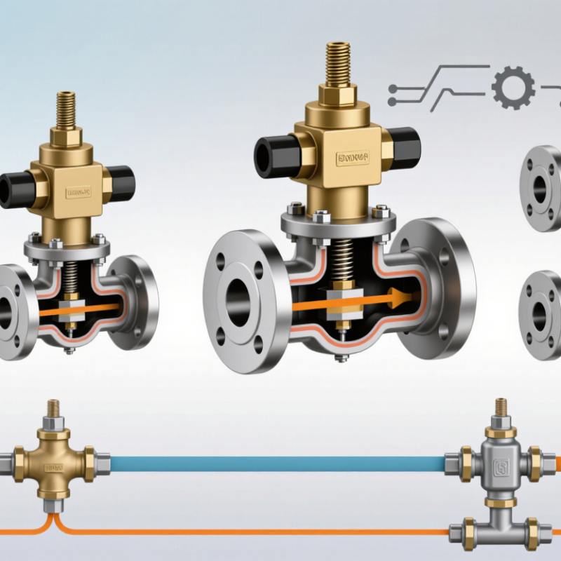
A Process Gas Solenoid Valve controls gas flow through an electrically operated mechanism. It may look like a compact metal block, but its internal design affects response, sealing, and operating limits. Selecting a valve by name alone is rarely enough. Gas composition, pressure, temperature, flow rate, and connection size all matter.
This guide compares common designs, including direct-acting and pilot-operated valves, normally closed and normally open configurations, and two-way and three-way arrangements. These labels describe different features, so a valve can belong to several categories at once. That detail is easy to miss. It can also lead to poor comparisons.
Direct-acting models can operate without a pressure difference, while pilot-operated designs often use process pressure to assist opening. Normally closed valves shut when de-energized; normally open models behave differently. Two-way valves control a single flow path, while three-way versions can redirect flow. Diaphragm and piston constructions bring further differences in sealing and service needs.
The best choice depends on the actual process, not a generic ranking. Check the manufacturer’s specifications for gas compatibility, allowable pressure and temperature, coil voltage, and leakage rating. A datasheet does not tell the whole story, though. Installation conditions and maintenance access deserve attention too. This overview explains what to compare, where each type may fit, and which questions to resolve before specifying a valve.
What Are the Top Types of Process Gas Solenoid Valves?
Direct-Acting Solenoid Valves for Process Gas
A direct-acting solenoid valve opens when its energized coil moves a plunger away from the valve seat. When power stops, a spring usually returns the plunger and closes the passage. The valve does not rely on process pressure to operate, so it can work where pressure is low or differential pressure is limited. That makes it useful for analyzer lines, purge circuits, and small gas sampling systems. Compact and responsive, it can provide clear on-off control. Check the rated pressure and gas compatibility before installation.
Selection still needs care. Match the valve’s seal materials to the actual gas, temperature, and moisture level. Confirm whether the system needs a normally closed or normally open valve, then check voltage, duty cycle, orifice size, and flow capacity. A direct-acting design may need greater coil force as pressure or orifice size increases. Larger flow requirements can therefore mean more heat or power use. Sizing is not always neat; a valve that fits the pipe may still restrict flow.
Tips: Keep the line clean, and check for particles that could prevent the seat from sealing. Measure voltage at the coil during operation, not only at the power supply. Test several cycles under real operating conditions. “Gas compatible” is not specific enough; verify the exact gas and seal combination.

In high-flow gas systems, a pilot-operated solenoid valve uses the gas pressure itself to help open its main valve. An electrical coil moves a small pilot plunger, releasing pressure above a diaphragm or piston. The resulting pressure difference lifts the main seal. This design can control substantial flow without requiring an equally large, power-hungry coil.
The pressure range matters. Many pilot-operated models need a minimum pressure difference to open reliably, so they may not suit low-pressure or zero-pressure service. Check the valve’s specified operating range against actual startup and running conditions. A pressure gauge near the valve can reveal drops that a system diagram misses. Small details count.
For example, a valve controlling a gas header may cycle as nearby equipment starts and stops. Frequent switching, contaminated gas, or a mismatched seal material can affect performance over time. Match the body and seal materials to the gas, temperature, and pressure, then confirm the flow capacity and coil rating. Do not size by pipe diameter alone. A larger valve is not automatically better; poor sizing can cause unstable control or slow response. Installation orientation and maintenance access deserve attention too, though they are easy to overlook. When conditions fall near a model’s limits, verify the selection with its technical documentation and a qualified process engineer.
| Valve type | How it operates | Pressure differential requirement | Flow suitability | Typical process-gas applications | Key selection considerations |
|---|---|---|---|---|---|
| Direct-acting | The solenoid directly moves the sealing element to open or close the orifice. | Can generally operate from zero differential pressure, subject to the valve’s rated pressure limits. | Usually suited to smaller orifices and lower flow capacity than comparable pilot-operated designs. | Small gas lines, instrument-gas duties, and applications where the available pressure differential is low or variable. | Check coil power, pressure rating, orifice size, gas compatibility, and the required fail position. |
| Internally pilot-operated | The solenoid opens a pilot passage; process pressure then helps move the main diaphragm or piston. | Requires a minimum pressure differential specified for the particular valve. | Well suited to higher flow through larger ports, with relatively low electrical power compared with directly moving a large main element. | Pressurized gas distribution, burner trains, and other on/off duties with a dependable inlet-to-outlet pressure differential. | Confirm minimum differential pressure, flow direction, gas cleanliness, and whether the valve can open against the actual system conditions. |
| Externally pilot-operated | A separate external pilot-pressure source actuates the main valve, rather than relying solely on the pressure difference across the main port. | Main-line differential requirements depend on the design; a suitable external pilot supply is required. | Can serve larger-flow duties where the valve is designed for the required port size and operating conditions. | Gas systems where main-line pressure is insufficient or unsuitable for operating an internally piloted valve. | Verify pilot-gas pressure and quality, tubing arrangement, venting requirements, and the consequences of losing pilot supply. |
| Assisted-lift (kick-off) pilot-operated | The solenoid mechanically assists the initial lift, after which pilot action and process pressure help open the main element. | Some designs can operate at lower differentials than conventional internally piloted valves; the specified minimum still applies. | A potential option for larger flow paths when low or fluctuating differential pressure is also a concern. | Gas duties needing a combination of a relatively large port and broader differential-pressure capability. | Operating range and performance vary by construction; check the manufacturer’s pressure, temperature, and flow data. |
| Normally closed or normally open configuration | Describes the de-energized state: normally closed valves block flow, while normally open valves allow flow, subject to the specific design. | Depends on the underlying direct-acting or pilot-operated mechanism. | Available flow capacity depends on the valve architecture, port size, and gas operating conditions—not on the normal-state designation alone. | Chosen to match the required safe state during power loss or control-system shutdown. | Assess the process hazard and shutdown philosophy; do not treat “normally closed” or “normally open” as a substitute for a full safety review. |
Note: Actual flow capacity and operating limits depend on gas properties, pressure and temperature, port size, valve construction, and the manufacturer’s rated data. Confirm compatibility with the process gas and applicable codes before selection.
Semi-direct-acting valves suit process gas lines where inlet pressure rises and falls. A moving plunger mechanically assists the diaphragm, helping the valve open even when pressure differential is low. This can avoid the minimum-pressure requirement common in pilot-operated designs.
Useful in practice. For example, a gas cabinet may see pressure changes as cylinders empty or regulators switch.
SEMI’s 2024 equipment forecast put global semiconductor manufacturing equipment sales at $109 billion for 2024, rising to $113 billion in 2025. That forecast signals continued investment in complex production systems, where stable gas delivery matters; it does not measure valve demand.
When specifying a valve, compare the minimum and maximum pressure differential, flow coefficient, response time, seal compatibility, and coil duty rating. Check these values against the actual gas and operating cycle. A semi-direct design is not automatically the best choice.
I would verify performance at the lowest expected pressure, not only at nominal conditions. Small details matter. A valve that works on a clean bench may respond differently after heat, vibration, or repeated cycling.
Normally closed (NC) process gas solenoid valves block flow when the coil is de-energized. Applying power opens the valve, making NC designs useful when a power loss should stop gas flow. Imagine a burner line that must shut when its control circuit drops out. The valve’s actual closing time and leakage rating still matter; “normally closed” alone does not guarantee a safe installation.
Normally open (NO) valves allow flow without power and close when energized. They may suit systems where continued flow is the preferred failure state, but that choice needs a documented hazard review. The U.S. Department of Energy’s Improving Compressed Air System Performance sourcebook reports that compressed-air systems use about 10% of industrial electricity on average, with some facilities reaching 30%. This figure concerns compressed air, not every process-gas system, but it highlights why operating duty and leakage deserve attention. Small details matter.
Tips: Confirm the required state during power loss, then check gas compatibility, pressure range, temperature, and allowable leakage. Match the valve to the actual flow direction and switching frequency. A label can look reassuring; it is not a substitute for testing the installed assembly under expected conditions.
In hazardous process areas, a solenoid valve must control gas flow without becoming an ignition source. An explosion-proof model uses a protective enclosure designed to contain an internal ignition and limit its spread. That does not make every valve suitable for every location. The protection rating, gas group, temperature limits, and installation method must match the actual service conditions.
Look beyond the enclosure. Check that the valve’s seals and internal materials suit the process gas, pressure, and temperature. Confirm the coil voltage and duty cycle, too. A poorly matched coil can overheat, while incompatible seals may harden or leak. Small details matter. Cable entries, conduit fittings, grounding, and cover seals need careful installation and regular inspection; a strong enclosure cannot compensate for a loose connection.
Think through failure behavior before selecting a valve. Should gas flow stop during a power loss, or is another response required by the process design? Verify that the valve’s flow capacity and response time fit the line, rather than relying on port size alone. Area classifications and accepted protection methods vary, so consult qualified engineering guidance and applicable local requirements. It is easy to focus on the valve body and overlook the wiring route. That oversight deserves a second look.
© 2023 JEM Electronics, Inc. – United States Cable Assembly. All rights reserved.