Why Choose Industrial Vacuum Piping for Your Business?
Industrial Vacuum Piping can help businesses move dust, trim, powders, and process waste through enclosed lines. It can reduce manual handling and keep material moving toward a central collection point. Picture a production floor where operators no longer push bins between workstations. The benefit, however, depends on the design.
Pneumatic conveying expert David Mills, author of Pneumatic Conveying Design Guide, offers a relevant principle. A fair paraphrase of his design guidance is: “Match the conveying system to the material and operating conditions, not the other way around.” Particle size, moisture, bulk density, and the route all matter. A tight elbow may increase resistance. A poorly placed branch can affect flow. These details deserve attention.
There are trade-offs. Vacuum lines need suitable pipe sizing, reliable filtration, and access for inspection. A system that looks tidy on a drawing may be awkward to clean or maintain. That is easy to overlook. Before choosing equipment, businesses should review the material, collection points, operating schedule, and future changes with a qualified engineer. Real site measurements matter more than assumptions. Industrial Vacuum Piping is not a universal fix, and the right layout may require revision after operators test it. A thoughtful design can support cleaner handling and steadier production—but only when it fits the work.
Industrial Vacuum Piping: Components, Layout, and Material Movement
Why Choose Industrial Vacuum Piping for Your Business?
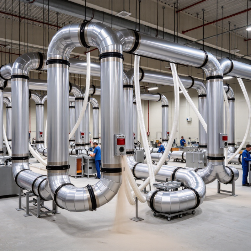
Industrial vacuum piping moves dust, chips, granules, or other process material from pickup points to a collection unit. A typical system includes pipe, bends, branches, valves, filters, and a vacuum source. Each component affects airflow. For example, a tight bend can increase resistance, while an undersized branch may leave material behind. Pipe diameter and routing should match the material, conveying distance, and required pickup rate. A site assessment by a qualified engineer can help verify these choices.
Layout matters on the factory floor. Keep runs as direct as practical, limit unnecessary bends, and allow access to cleanouts and inspection points. Routes must also avoid obstructing walkways, equipment, and maintenance access. Material properties deserve attention: fine powders and heavier particles behave differently, and moisture can cause buildup. Even a well-designed system may need adjustment after installation; actual operating conditions can differ from initial estimates.
Tips: Map pickup points and note the material handled at each one. Check bends, joints, and filters during routine inspections. Watch for reduced suction or recurring blockages. These can signal a leak, buildup, or a layout issue. Keep records of changes, too. Small details get missed.
Why Choose Industrial Vacuum Piping for Your Business? — Components, Layout, and Material Movement
| System Dimension | Typical Components or Design Consideration | How It Supports Material Movement | Practical Business Consideration |
|---|---|---|---|
| Pickup points | Hood, floor inlet, tool connection, or machine-side pickup connected to the piping network | Captures dust, chips, or other compatible material near its source and directs it into the system | Position and size each inlet for the task; poorly placed pickups can reduce capture effectiveness |
| Piping network | Branches, main headers, elbows, reducers, tees, and supports | Provides a defined route from collection points to the separator or receiver | Keep routing as direct as practical and avoid unnecessary bends, abrupt changes, and long runs |
| Pipe material | Material selected for the conveyed substance, temperature, wear, grounding, and operating conditions | Forms the pathway through which the air-and-material stream travels | Metal piping is commonly used in industrial settings; abrasive, corrosive, combustible, or hot materials may require specific engineering review |
| Airflow and conveying velocity | Fan or vacuum source, duct sizing, system balancing, and operating controls | Maintains the airflow needed to carry the intended material through the network | Required conditions depend on material properties and layout; undersized or unbalanced systems can lead to settling or poor pickup |
| Separation and collection | Separator, cyclone where appropriate, filter, receiver, and discharge arrangement | Separates conveyed solids from the air and collects material for disposal or reuse | Select filtration and collection equipment for particle characteristics, dust loading, and applicable emissions requirements |
| Branch isolation | Manual or automatic gates and valves at selected branches | Allows airflow to be directed to active pickup points while limiting unused branches | Coordinate valve positions and operating procedures to keep the system within its designed airflow range |
| Material handling | Hoppers, bins, rotary airlocks, or other compatible discharge equipment | Transfers collected material from the receiver to storage, disposal, or the next process step | Discharge equipment should suit the material’s flow behavior and the required containment or process connection |
| System layout | Pickup locations, pipe routes, access points, and space for equipment and maintenance | Connects work areas to the collection equipment with a planned path for material transport | Allow access for inspection and cleaning; account for future equipment changes and avoid obstructing walkways |
| Inspection and maintenance | Accessible cleanouts, inspection points, filter monitoring, and scheduled checks | Helps identify deposits, leaks, blockages, or filter loading that can interrupt material movement | Set maintenance intervals according to operating conditions, material type, and equipment guidance |
| Safety and compatibility | Grounding and bonding where required, suitable components, and a hazard assessment | Supports controlled movement of material through equipment selected for the application | Combustible dust and other hazardous materials require application-specific assessment and compliance with relevant codes and regulations |

© 2023 JEM Electronics, Inc. – United States Cable Assembly. All rights reserved.