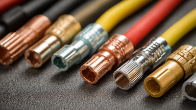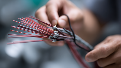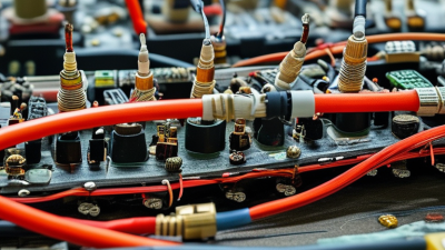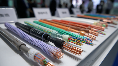
A connector can look correct on a drawing and still fail beside a hot engine, under road vibration, or after repeated service. Choosing wire harness connectors is therefore more than matching pin count. The decision affects electrical performance, assembly time, repair access, and long-term reliability. Small details matter: wire gauge, terminal plating, seal compression, and the force needed to mate two halves.
The scale of the market raises the stakes. Grand View Research’s 2024 Automotive Wiring Harness Market report projects continued market growth through 2030, reflecting the expanding role of electrical systems in vehicles. That growth does not make every connector suitable. A high-current terminal may be unnecessary in a low-voltage sensor circuit, while an underspecified seal can invite moisture into a connector exposed to spray. Robert Mroczkowski, an interconnection consultant and author of the Electronic Connector Handbook, offers a useful principle in his technical work: connector selection must account for the application’s electrical and environmental demands. This is a paraphrase, not a verbatim quotation.
Start with the real operating conditions. Check current, voltage, temperature range, vibration, contamination, and expected mating cycles. Then compare terminal size, retention, sealing, and available tooling against the harness design. Verify ratings in the manufacturer’s datasheet; catalog summaries can leave out important limits. A connector that fits is not automatically a reliable choice. That distinction is easy to miss. The outline below turns these checks into a practical selection process, while leaving room to question assumptions before parts reach the production line.
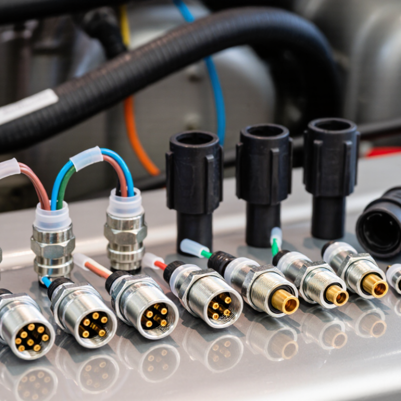
Define the harness’s actual job before comparing connector styles. A cabin sensor, an underbody actuator, and a machine-room motor face very different conditions. Record voltage, current, wire size, mating frequency, and available space. Then map the surroundings: temperature peaks, water spray, dust, oil, vibration, and cleaning chemicals. Small details matter. A connector beside a hot exhaust may need different materials and clearance than one behind a dashboard. Do not rely on average conditions alone; startup loads and brief temperature spikes can be easy to miss.
Use test criteria that match the installation. IEC 60529 defines the IPX7 enclosure test as temporary immersion in water, typically to a depth of 1 meter for 30 minutes. That rating does not prove resistance to oil, salt spray, or repeated pressure washing. For road-vehicle equipment, ISO 16750-3:2023 addresses mechanical loads such as vibration and shock; select test conditions based on the component’s mounting location. A connector on a vibrating frame needs secure locking and strain relief, not just a high current rating. I would also verify the assembled harness, since seals can be pinched during installation. Paper specifications help, but real routing can be less tidy. Check bend radius, service access, and whether technicians can inspect the latch without removing nearby parts.
Start with the circuit’s real operating conditions, not just its nominal voltage. Record maximum current, voltage, ambient temperature, and expected electrical load. Then check the wire gauge, contact rating, and allowable voltage drop together. A connector that fits the current on paper may still overheat inside a sealed enclosure. Small details matter.
The International Energy Agency’s Global EV Outlook 2024 reports that electric car sales exceeded 14 million in 2023, nearly 18% of global car sales. That growth makes careful selection of high-voltage connectors increasingly relevant, especially where insulation, spacing, and touch protection are critical.
Mechanical requirements deserve equal attention. Measure the available space, cable exit angle, mounting method, and expected mating cycles. A latch should remain secure under vibration, yet be accessible for service. Check sealing needs against the actual environment: IEC 60529 defines the IPX7 test as temporary immersion in water up to one metre for 30 minutes. That rating does not guarantee protection against every spray, chemical, or temperature change.
Fit matters, too. IPC/WHMA-A-620 provides workmanship criteria for cable and wire-harness assemblies, including inspection of crimps and connections. Use it as a reference alongside the connector manufacturer’s specifications. A tidy drawing can still miss a tight bend radius or awkward repair access. Recheck the assembly in its installed position.
Choose a wire-to-wire connector for a removable harness section; use wire-to-board types where cables meet a circuit board. Circular housings can suit vibration-prone equipment, while sealed rectangular connectors often simplify multi-circuit layouts. Fit matters. Check pin count, wire gauge, current, and available space before choosing. Grand View Research estimated the global electrical connectors market at USD 84.73 billion in 2023, with a projected 5.6% annual growth rate from 2024 to 2030. That broad demand makes connector choice important, but market growth alone cannot tell you which part fits your application.
Material selection should follow heat, moisture, chemicals, and vibration at the installation point. Copper-alloy terminals with suitable plating help manage conductivity and corrosion; PA66 or PBT housings are common choices where heat resistance matters. Seals need to match exposure, not just look robust. A silicone seal may help block moisture, but poor wire sizing can still leave a leak path. Small detail.
Look for a primary latch that gives a clear, tactile click, then consider a secondary lock or terminal-position assurance feature. These help prevent terminals backing out during assembly or service. Check that the latch remains accessible after installation. A strong lock can become a nuisance when technicians must disconnect it repeatedly; this trade-off is easy to overlook in a clean drawing. Verify retention and sealing against the harness’s actual conditions, rather than relying on appearance alone.
Choosing the right wire harness connector starts with compatibility. Match the pin count, layout, keying, and wire gauge to the harness and equipment. Check the connector’s rated current and voltage against the circuit’s actual load. A plug may fit but still make a poor electrical connection. Small mismatches matter.
Next, consider where the connector will operate. An IP rating can indicate resistance to dust and water, but it does not cover every exposure. Heat, vibration, oil, salt spray, and repeated washing may require additional material or performance checks. Review the specified temperature range and mounting conditions. A connector used inside a dry panel may not survive beneath a vehicle. I have seen this overlooked.
Safety standards matter too. Confirm that the connector and wiring meet the standards required for the product and its intended market. Check documentation, test conditions, and any limits on voltage or temperature; a rating is meaningful only within its stated conditions. Do not rely on appearance alone.
Tips: Before ordering, compare datasheets line by line. Photograph the existing connector, including its latch and pin arrangement. If the application is uncertain, test a sample under realistic conditions. That extra step can feel fussy, but guessing is worse.
| Selection Dimension | What to Check | Practical Guidance | Why It Matters |
|---|---|---|---|
| Connector-family compatibility | Series, housing size, contact layout, gender, and mating interface | Confirm the connector manufacturer’s part drawings and compatibility documentation. Similar-looking housings are not necessarily interchangeable. | A mismatch can prevent mating, damage contacts, or create an unreliable connection. |
| Keying and polarization | Key positions, guide features, locking latches, and color or mechanical coding | Choose a configuration that prevents incorrect mating in the finished harness. Verify that the mating halves use the same keying arrangement. | Polarization helps prevent misconnection and resulting electrical or equipment damage. |
| Terminal and wire compatibility | Terminal type, conductor material, wire size, insulation diameter, and approved crimp range | Use terminals specified for the connector housing and the actual wire construction. Check both conductor and insulation crimp requirements in the applicable tooling documentation. | A terminal may fit the housing but still make a poor electrical or mechanical connection if it is unsuitable for the wire. |
| Current and voltage ratings | Rated current per contact, number of loaded contacts, operating voltage, and circuit protection | Use ratings for the complete configuration, including contact size, wire size, ambient temperature, and adjacent loaded contacts. Do not assume the single-contact rating applies to every populated connector. | Current creates heat; exceeding applicable limits can cause excessive temperature rise, degradation, or failure. |
| Environmental ingress protection | IP rating under IEC 60529 and whether the rating applies when mated, unmated, or with accessories fitted | For example, IP67 indicates dust-tight protection and resistance to temporary immersion under the standard’s specified test conditions. IP68 immersion conditions are agreed or specified for the product. Check the exact test conditions and assembly configuration. | An IP code describes protection against specified ingress tests; it does not by itself establish resistance to chemicals, corrosion, or every outdoor condition. |
| Temperature and thermal limits | Operating temperature range for the housing, contacts, seals, wires, and other components | Confirm that the complete harness assembly is rated for the expected minimum and maximum temperatures. Consider current-related heating and nearby heat sources. | The usable temperature range is limited by the components and conditions in the actual assembly, not just the connector housing. |
| Vibration and mechanical retention | Primary latch, secondary lock, terminal retention, strain relief, and application-specific vibration requirements | For vehicle or machinery use, check test evidence for the applicable application and ensure the harness is supported so that connector contacts do not carry cable loads. | Vibration, movement, and cable pull can contribute to fretting, intermittent connections, or terminal back-out. |
| Sealing and corrosion protection | Seal compatibility, mating seal condition, cavity plugs, plating, and exposure to moisture or salt | Use the specified seals and plugs, and follow assembly instructions for wire diameter and seal installation. Verify that material and plating choices suit the exposure. | Incorrect sealing or unsuitable materials can allow moisture ingress or corrosion even when the connector family has a stated environmental rating. |
| Applicable safety and performance standards | Standards named in the product documentation, end-product requirements, and jurisdiction-specific regulations | Depending on the application, relevant references may include IEC 61984 for connector safety, IEC 60529 for IP enclosure ratings, UL 1977 for component connectors, or USCAR-2 for automotive connector performance. Confirm scope, edition, and required certification with the project specifications. | A standard’s applicability depends on the connector type and end use. A reference to a standard is not, by itself, proof that a particular assembly is certified or compliant. |
| Assembly and serviceability | Crimp tooling, insertion and extraction procedures, inspection access, and replacement requirements | Check that qualified tooling and repair instructions are available. Define inspection criteria for crimp quality, terminal seating, latch engagement, and seal placement. | Correct assembly and inspection help maintain repeatable electrical and mechanical performance over the harness life. |
Selection note: Verify ratings and compatibility against the current technical documentation for the exact connector, terminals, wires, seals, and assembled configuration. The required design limits and compliance evidence should be determined from the application and applicable regulations.
A connector can look correct and still fail once the harness is installed. Check the keying, latch engagement, terminal retention, and bend clearance with the actual wire gauge and enclosure. A gentle tug on each wire can reveal a terminal that has not locked.
Small detail. Then mate and unmate the connector several times, watching for uneven force, damaged seals, or a latch that catches only at an angle. Record the results; memory is a poor test instrument.
Measure electrical performance under load, not just continuity. IEC 60512-2-1 describes a millivolt-level method for measuring contact resistance, which helps detect resistance at the contact interface. Record resistance and voltage drop before and after repeated mating, then repeat the measurements after vibration or temperature exposure relevant to the application.
SAE J2030 provides performance tests for heavy-duty electrical connectors, while IPC/WHMA-A-620E gives workmanship criteria for cable and wire harness assemblies. These references help shape a test plan; they do not replace application-specific limits. A brief bench test may miss a problem that appears after hours of vibration. That is easy to overlook. Keep the test setup, load, cycle count, and readings together so another technician can reproduce the check.
© 2023 JEM Electronics, Inc. – United States Cable Assembly. All rights reserved.